Содержание
- 1 Module development guide
- 1.1 Definitions
- 1.2 Module concept
- 1.3 How to start developing the module
- 1.4 Module structure
- 1.5 Creating the module interface
- 1.6 Interface design standard
- 1.7 Basics of working with scripts
- 1.8 Creating a subdevice
- 1.9 Adding a widget to a subdevice
- 1.10 Work with channels and tags
- 1.11 Setting a module in the app
- 1.12 Typing a module using the Smart API
Module development guide
Definitions
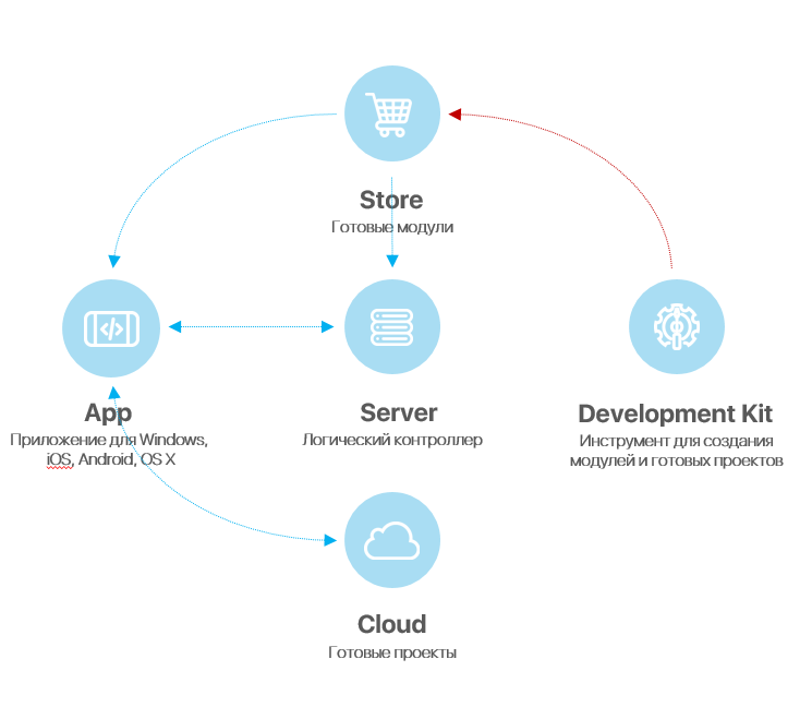
Module - is a component that allows you to control one type of equipment by its unique ID. The module is located in the store of modules.
Control panel (mobile device) - is a device from which the project i3 lite is launched (tablet, smartphone).
Store of modules - is a cloud server for uploading ready-made modules. The module store is available from the i3 lite application or on oursite
iRidium Studio - is a editor that allows to create the module to control device for i3 lite application. You need to use a special editor build for module developers to develop the module
i3 lite - is an application to create, set and use i3 lite projects.
i3 lite project – is an automation project made up of ready equipment control modules. i3 lite projects differ from i2 Control projects: i3 lite projects can be edited dynamically without prior editing in iRidium Studio. i3 lite project consists of several small parts that can be put together into a single whole in i3 lite app with the help of the built-in constructor. It can also be easily edited in the app. As a result, a big number of intermediate processes are no longer necessary, such as installing software on PC, uploading projects on contol panels. All is done in one place - a control panel.
SubDevice - This is a virtual representation of the working area of the physical device. If we take as an example a 6-channel dimmer it has 6 sub-devices, because each independent device requires a separate control interface and connects to one channel.
Room (in i3 lite) - The visual part of i3 lite containing hardware management widgets. The project in i3 lite consists of rooms located on the floors
Widget - is a visual module component located in the room. It has limitations in size and fixed position in the room interface. It contains the main module functionality. For additional functions Remote is used.
Remote - is a visual module component which is hidden by default. It opens only when clicking on the corresponding item of the widget. It does not have size limitations (not more than the panel display size) and can be located in any part of the room interface (it is usually located in the middle of the panel display). It contains additional functionality of the module.
Macros - is a sequence of commands of various modules, which is activated by pressing. Contains "Action" and "Condition". For example, the macros "turn off all the lights in the house" will send the shutdown command to all devices responsible for lighting.
Routine - is a sequence of commands of various modules, which is activated automatically when a certain event occurs. Contains "Event", "Action" and "Condition". For example, "turn on the light if the motion sensor is triggered"
Event - is a routine component that describes the control command and the value range. If the value is sent in the indicated range, the routine is executed. For example, the event "Motion appeared" is activated if the motion sensor is triggered.
Action - is a component of macros and routines. It describes the control command and value that must be sent to the command. For example, "turn on the light". There are 2 types of Action: Simple Action and Advanced Action.
Simple Action - Simple Action is used when the command and Action value are known in advance.
Advanced Action - Advanced Action is used when the command is known but the value is unknown. The value is set dynamically when Action is used in i3 lite (but not when creating in iRidium studio).
Condition - is a component of macros and scenes. It describes the control command and value range. When a value from the value range is sent Action is executed.
Scanner - is a software part, that analyzes any bus looking for connected devices. Found connected devices are displayed in a list. Modules for the found devices are downloaded from iRidium store and the devices become available to control in i3 lite.
Module concept
The module is an independent subroutine of the i3 lite application which is built in the project and has an independent interface, driver and logic. Modules are developed in the iRidium Studio editor and located in the module store iRidium Store. Integrator downloads the module from the module store for each individual project.
There are two types of modules:
- Control module - module for hardware control
- Scanner - module for searching hardware in the local network and loading modules for found devices
How to start developing the module
Before starting your work, it is recommended to read iRidium documentation. It describes the basics of working with iRidium. The i3 lite documentation describes how to develop modules for the i3 lite platform for users, who already know iRidium. If you want to write script use i3 lite API.
The module life cycle consists of:
- Developing the graphic part in iRidium studio
- Developing the driver part (scripts, devices)
- Testing
- Publishing in iRidium store
- Using (module download via the i3 lite application from the cloud and adding to automation projects)
Module structure
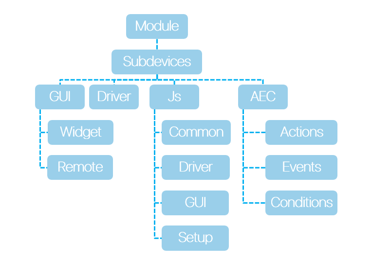
Each module must consist of subdevices. The subdevice is a virtual representation of the working area of a physical device. Many devices support multiple workgroups with the same functionality. Each workgroup may be in a separate zone. To fully control the zone, you need to create a subdevice for each workgroup of the device. For example, a 6-channel HDL dimmer contains 6 dimmable channels, through which 6 working groups can be controlled. Therefore, it is advisable to select in the module 6 subdevices for the possibility of creating actions, events and conditions for each workgroup separately. The presence of subdevice in the i3 lite module is obligatory. The number of sub-devices can be from one to many. Usually the number of subdevice is equal to the number of channels of the controller, the number of its work areas or logical devices.
Subdevice consists of:
- Conditions
- Actions
- Events
- Widgets
Conditions, actions and events are logical elements of the subdevice, on their basis macros and routines are created. Widget is a graphical element, through which the user will control subdevice. Usually one subdevice contains one widget, but the number of conditions, actions and events varies (from zero to many). The number of subdevices in the module can be either fixed or not. For example, you can develop a module only for a 6-channel dimmer, and you can make a module that will request the hardware for the number of subdevices and create the required number of subdevices.
Creating the module interface
The interface part of the midule consists of:
- widgets - interface part of the subdevice, which is located in the rooms and has basic control functions
- Remote - interface part of the module, which has a set of device functions and opens to the full screen, when you click on the widget button
- Authorization window - Authorization is required to work with some devices. To do this, the developer can create a special authorization window that is available in the module settings
- The module settings window is a window where you need to enter the parameters for the module operation
картинка окна настроек модуля и кнопки открытия The whole graphic part is drawn in the graphical interface of the iRidium studio editor. In contradistinction to i3 pro, the module's interface should be made up of ready-made graphic components located in the gallery.
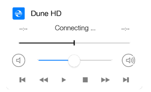
Widget
Widget is a visual component of the module, a kind of Popup that will be displayed in the room. The main task of the widget is to display the basic controls of the subdevice and to provide a module transition to the Remote control of the subdevice. For example, to control a media player, you can place a volume slider or Mute button for quick access to adjusting the volume. The weather widget can display the current weather, and the control panel will contain the weather forecast for all 5 days.
The module does not make sense without widget, because it will not have a graphical representation in the i3 lite project.
Widget has a limited size
- Width 640
- Height can not exceed 1200
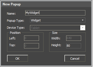
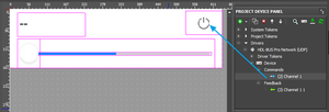
To create a widget, click the Add pop-up button in the Project overview panel and in the appeared menu select popup type: "Widget", set the name and properties:
Properties of a created widget can be changed with the help of Object Properties.
Graphic items are assigned to channels like in popups:
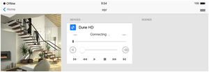
Widget will be displayed:
- In the room when a client uses the project
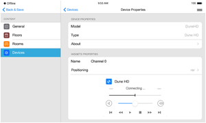
- In the module settings when it is added to the project:
Remote and other graphic windows
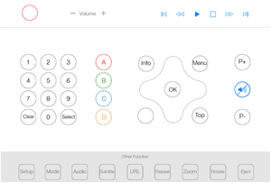
Remote (a remote control) is a graphical area to control SubDevices. Unlike wigets, it can have free size and position. And it is displayed on call. Remote is displayed when a button to go to the remote control is pressed on a widget.
Items to control equipment are placed on Remote (buttons, lists, switches, levels). There can be from 0 to several remote controls. Example of Remote:
Remote is created like a Widget. The only difference is to select "Remote" when you click "Add Popup Page" in the "Device Type" property.
Interface design standard
For the convenience of interface design, a standard was developed in which graphic windows should be developed in the module so that the modules of different developers looked uniformly within the framework of one project.
Basic principles
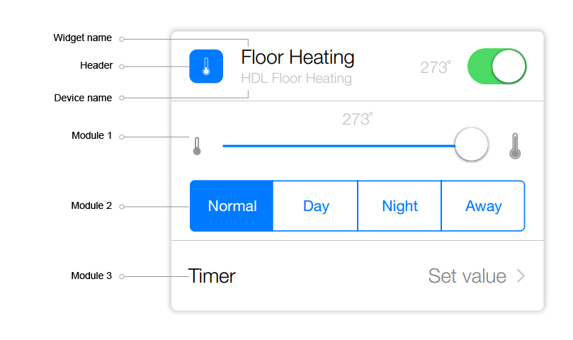
A widget consists of a "Header" and additional modules of the main functional.
"Header" - the top module of the widget.
"Header" contains:
- the name of the widget;
- the name of the device, that
is controlled by the widget;
- icon of device category.<b r/>
The additional modules contain items to contol the device.
Module grid and blocks
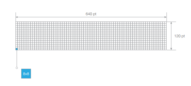
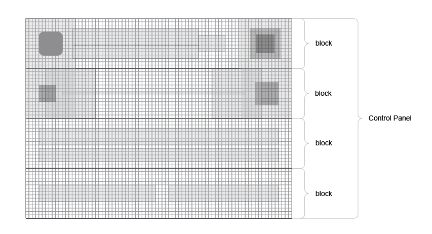
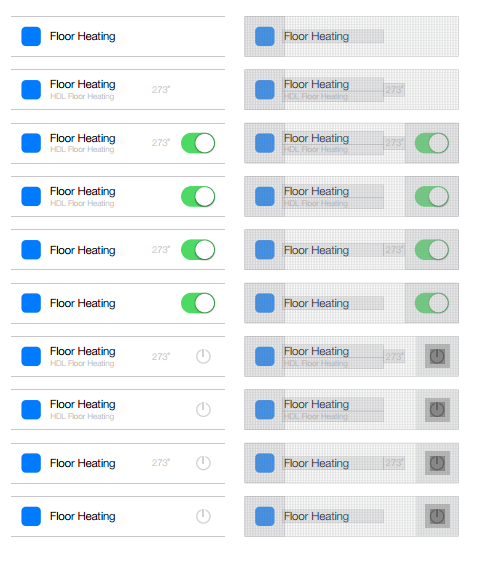
Module grid widget is a block 640 pt wide And 120 pt in height. Each block has a grid of 8x8 pt. The rounding of the corners is 12.5 ut. (Circle 25)
The principle of constructing a widget block is a constructor from Controls (buttons, switches, labels) from smaller to larger.
Buttons
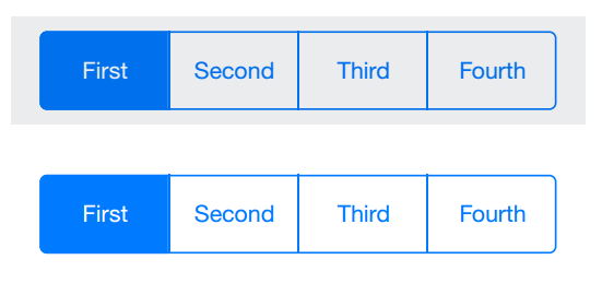
Toggle
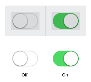
Switch
Multistate
Arrow-button
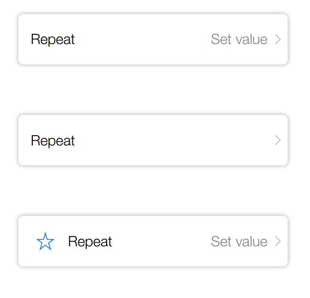
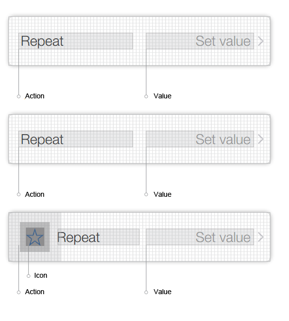
Button action
When the button is pressed, a «PopUp» is called.
«PopUp» Contents
«Input field», «Single selection», «Multiple selection».
Sliders
Description
Icons
All icons are devided by their spheres of use, their main differene is the size.
«Header» widget
Icon location
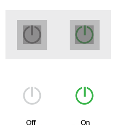
All buttons have two states - active and inactive
When the button in inactive the color is always # 848484 or RGB 132
The state of a button is considered active, when the action received feedback and is short or instant (e.g. «Play» in a media player) or an acrion that is active for a long time and demands another activity to switch off the active state (e.g. «Repeat» in a media player).
Basics of working with scripts
To design an interface and to add a driver, you are to develop the logics of module work via script. The script part of developing i3 lite modules has a number of special features. Before developing the script part of i3 lite modules, please, read iRidium Pro API and i3 lite API.
A module can contain any number of scripts. There are several types of scripts for modules:
- Driver - script files of this type contain script, responsible for working with a driver
- GUI - script files of this type contain script, responsible for working with graphics
- Common - script files of this type must contain general scripts, such as a set of additional functions or a description of classes of secondary importance
- Setup - a special script file that contains information about module setting, a list of fields that are obligatory to fill in, types of these fields and functions that check the correctness of entered data.
Devision into types is necessary for the module correct work on the server. Only logics and the driver part work on the server, but the server knows nothing about the graphic part. That's why a module developer has to devide scripts into types. The server does not notice files for working with the graphic part.
When modules are developed module names have to be used instead of IR. Thus, a listener looks this way module.AddListener…
Every script file must start with a listener
module.AddListener(IR.EVENT_MODULE_START, 0, function(){});
It's a new type of events, intended for developing modules. When developing a module it's important to remember that a script file becomes closed for other script files. It means that variables and names with the same names can be used in different script files and they are not rewritten. But here a limitation appears - you can get access to a function from another file easily. To get access to a function from another script file, import the script file with the help of module.Import("FileName.js") command.
Example:
//Name_1.js - first js file
this.Text = "Hello, world!"; //Pointer to a text variable
//Name_2.js - second js file
var Text = module.Import("Name_1.js").Text; //Importing an object with a pointer to a text variable from the first js file
IR.Log(Text); //"Hello, world!" //log the text variable
Creating a subdevice
The basis of every module is subdevices. The task of every module developer is to define how many subdevices a module has and to develop the logics of subdevice work. Each subdevice may contain a widget, a remote control, a set of actions, events and states. All contents of a subdevice have to be indicated when a subdevice is created. Subdevice contents can't be changed during module work. The following command is used to create a subdevice:
module.AddSubDevice(SystemName, [Device], [System], [Type], [Tags], [Name], [Callback]);
where
SystemName - subdevice system name
Device - a driver to which a subdevice will be assigned
System - old parameter, "false" is to be used
Type - type of smart device. Parameter is under development
Tags - Array of virtual tag objects
Name - subdevice name that is displayed to the user
Callback function(){do somethings} - a function that is on till the IR.EVENT_ADD_SUBDEVICE event happens.
As a reply the function returns a link to a subdevice, that can be used to address it.
An example of creating subdevices for HDL Relay devices. The script checks th number of devices in the bus and creates subdevices.
for (var count = 1; count <= COUNT_CHANNEL; count++) {
      // Creating a subdevice
      l_oSubDevice = module.AddSubDevice("Relay " + count, HDL_SERVER, false, IR.SUB_DEVICE_TYPE_THROUGH_RELAY);
      // Creating StatusOnStart command
      if (count == 1)
         l_oSubDevice.AddChannel("Relay:statusOnStart", [ChannelData]);
      var l_sChannelName = "Relay:channel" + count;
      // Adding channels
      l_oSubDevice.AddChannel(l_sChannelName, [ChannelData]);
      l_oSubDevice.AddTag(l_sChannelName, [ChannelData]);
      // Add a virtual tag
      l_oSubDevice.AddVirtualTag("Power", 0, false, IR.SUB_DEVICE_TAG_POWER, true);
   };
Everything that is required can be added to a subdevice this way. An event is activated when a subdevice is created.
module.AddListener(IR.EVENT_ADD_SUBDEVICE, 0, function, [pointer]);
A link to a subdevice that was created is sent to a function. Different components can be added to subdevice in this event, such as, actions, events, states, widgets, chanels, tags. For example,
module.AddListener(IR.EVENT_ADD_SUBDEVICE, 0, function(in_oSubDevice){
      Creating actions
	  in_oSubDevice.AddAction("On", false, in_oSubDevice.SystemName + "_Power", lightID + "_1", IR.SUB_DEVICE_COMMAND_POWER_ON);
      in_oSubDevice.AddAction("Off", false, in_oSubDevice.SystemName + "_Power", lightID + "_0", IR.SUB_DEVICE_COMMAND_POWER_OFF);
      Creating events
      in_oSubDevice.AddEvent("On", "Drivers.PhilipsHue." + in_oSubDevice.SystemName + "_Power", false, "==", "1");
      in_oSubDevice.AddEvent("Off", "Drivers.PhilipsHue." + in_oSubDevice.SystemName + "_Power", false, "==", "0");
      Creating states
      in_oSubDevice.AddCondition("On", "Drivers.PhilipsHue." + in_oSubDevice.SystemName + "_Power", false, "==", "1");
      in_oSubDevice.AddCondition("Off", "Drivers.PhilipsHue." + in_oSubDevice.SystemName + "_Power", false, "==", "0");
   });
Thus, a developer can create the required number of subdevices when a module is installed or when new subdevices are added manually.
Adding a widget to a subdevice
After an interface is created in the studio and a function to add subdevices is added, create a copy of a widget for each subdevice and assign it to the subdevice. To assign a widget to a subdevice the following method is used.
SubDevice.addWidget(in_Widget)
The input parameter of the method is in_Widget - an object, a widget, created in the studio beforehand.
The output parameter of the method is True or False (successful or not).
For example, we have 3 lamps. Not to create a separate wiget for each lamp, use a ready template and clone it. Here is an example of creating widgets with the help of a code using the existing template .
Clone method allows to clone an existing popup.
Module.ClonePopup (in_Popup, in_Name)
The input parameters of the method:
- in_Name - name of a new widget.
- in_Popup - link to a popup.
The output parameter of the method is True, False.
module.AddListener(IR.EVENT_ADD_SUBDEVICE, 0, function(in_oSubDevice){
 var popup = module.GetPopup("Dimmer"); // Calling a widget that we want to clone
 // Creating a widget using cloning method
 var widget = in_oSubDevice.addWidget(module.ClonePopup(popup, "Dimmer"+ in_oSubDevice.Name));
 });
Names of new widgets must not be repeated
When a complete remote control is opened it is necessary to remmeber that a user will use the module both on a tablet and on a smart phone. The difference betwen the screen sizes makes a developer design 2 types of windows: a version for smart phones and a version for tablets. In addition a method must be added to the script that asks the system about the type of device where a module is launched and open the required window.
 if (IR.DisplayType == IR.DISPLAY_TYPE_PHONE) { //If a module is opened on a smart phone
    var l_oPopupScanner = module.GetPopup("Phone"); //show a popup created for a smart phone
  }
 else {
   var l_oPopupScanner = module.GetPopup("Tablet");//If a module is opened on a tablet, show a popup for a tablet
 }
Work with channels and tags
After creating a subdevice and adding a widget you must add to the subevice channels and tags required for its work. Like in i3 pro version, a driver can be added in the studio or via script. Each subdevice requires a personal set of channels and tags for the selected driver. You may work with the following three components:
- Channel. The following method is used to create a channel
SubDevice.AddChannel(Name, DataArray)
Name - channel name
DataArray - data array (specific for every driver)
- Tag The following method is used to create a tag
SubDevice.AddTag(Name, DataArray)
Name - tag name
DataArray - data array, specific for every driver
- Virtual tag. The following method if used to create a virtual tag
SubDevice.AddVirtualTag(Name, Value, [Edit], [smartID], [Hidden])
Name- name of a subdevice virtual tag
Value - Tag value
Edit - Permission to edit a tag
smartID - Parameter is under development! Set "false"
Hidden - Feature of a hidden tag
An example of creating channels and tags when creating a subdevice
l_oSubDevice = module.AddSubDevice("Light " + count, HDL_SERVER, false, IR.SUB_DEVICE_TYPE_THROUGH_DIMMER);

// Adding channel StatusOnStart
if (count == 1)
 l_oSubDevice.AddChannel("Dimmer:statusOnStart", [ChannelData]);

// Assigned to the variable name of the channel
var l_sChannelName = "Dimmer:channel" + count;

// Adding channels
l_oSubDevice.AddChannel(l_sChannelName, [ChannelData]);
l_oSubDevice.AddTag(l_sChannelName, [TagData]);

// Adding smart virtual tag
l_oSubDevice.AddVirtualTag("Power", 0, false, IR.SUB_DEVICE_COMMAND_POWER, true);
l_oSubDevice.AddVirtualTag("Power On", 0, false, IR.SUB_DEVICE_COMMAND_POWER_ON, true);
l_oSubDevice.AddVirtualTag("Power Off", 0, false, IR.SUB_DEVICE_COMMAND_POWER_OFF, true);
l_oSubDevice.AddVirtualTag("Level", 0, false, IR.SUB_DEVICE_COMMAND_LEVEL, true);
Setting a module in the app
Modules are stored in iRidium store and can be installed in the app using one of the following ways:
- With the help of a scanner
- Manually
Developing the Setup file
The Setup file must be developed for each variant. It's a special script file with fields that are required for module work. These fields can be device IP address, port, city name, etc. To develop a Setup file, create a new script file and select its type - "Setup". Eacn field is a tag and can be accessed from the script, and the input value can be received.
The Setup file consists of 2 parts. Part 1 is the driver settings. The settings must require IP addresses, ports and logins to connect the driver to a device. Part 2 is the module general settings, such as number of outputs, access keys. To set fields in the Setip file set the following fields in the script:
- Field type - indicate what field must be shown to a user (text field, data array, etc. Detailed description is given in API)
- Field name - name of field that a user sees when setting a module
- Default value - what value must be put by default
- Check function - a function to validate value in the field. A function must be written that checks the correctness of the entered data.
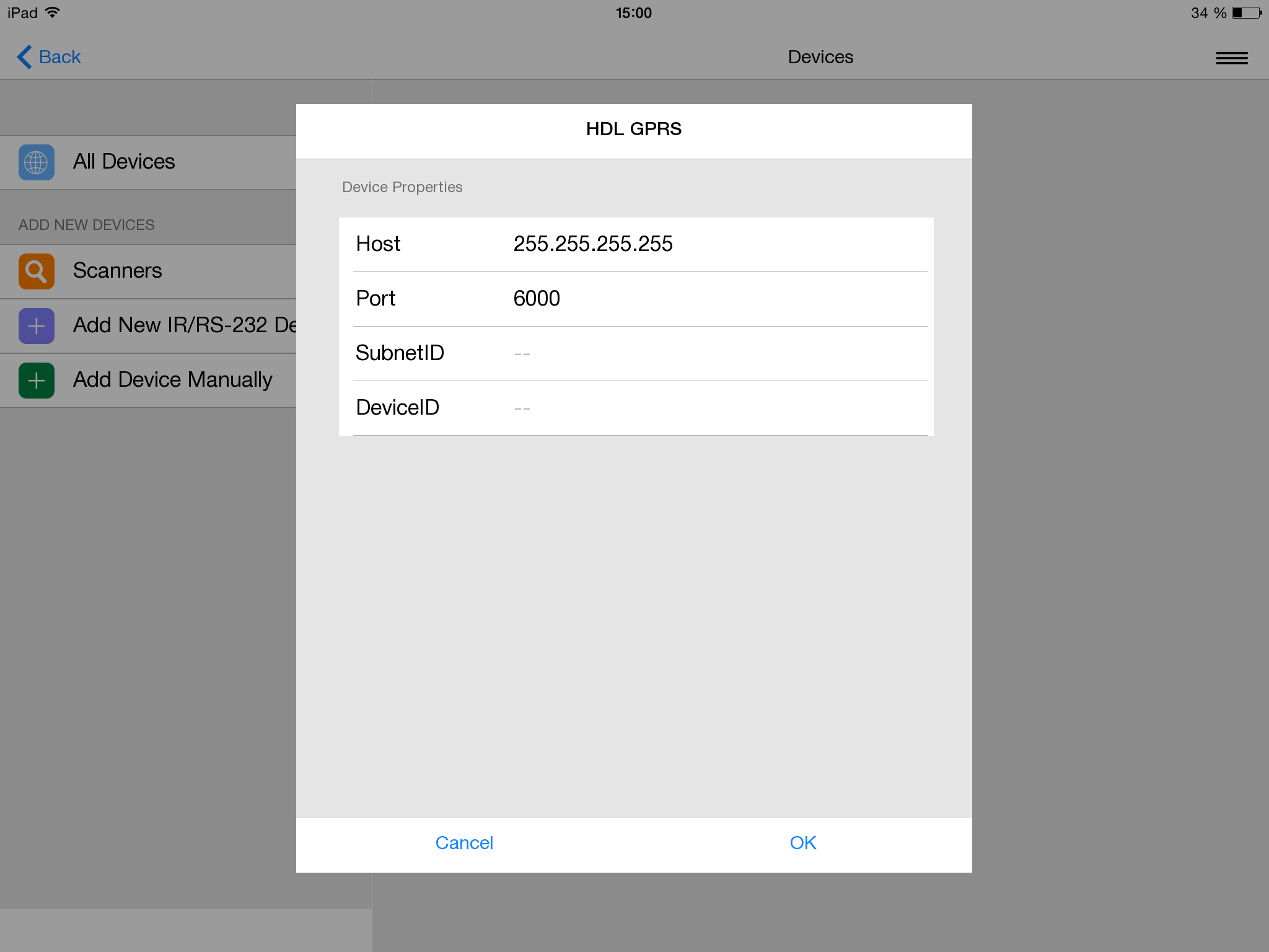
For example,"Setup" script for HDL module looks this way:
{
	// Data to connect drivers, created in Project Device Panel
	Drivers:
	[
      {
         Name: "HDL-BUS Pro Network (UDP)",
         Properties:
         [
            {
               Type: "textfield",
               Name: "Host",
               DefaultValue: "255.255.255.255",
               Validation: function(in_sValue) {
                  var l_aValueHost = in_sValue.split(".");
                  if (l_aValueHost.length != 4) {
                     return "Please input correct Host";
                  } else
                     if (parseInt(l_aValueHost[0], 10)>=0
                        && parseInt(l_aValueHost[0], 10)<=255
                        && parseInt(l_aValueHost[1], 10)>=0
                        && parseInt(l_aValueHost[1], 10)<=255
                        && parseInt(l_aValueHost[2], 10)>=0
                        && parseInt(l_aValueHost[2], 10)<=255
                        && parseInt(l_aValueHost[3], 10)>=0
                        && parseInt(l_aValueHost[3], 10)<=255
                     )
                        return 0
                     else
                        return "Please input correct Host";
               }
            },
            {
               Type: "textfield",
               Name: "Port",
               DefaultValue: "6000",
               Validation: function(in_sValue) {
                 if(parseInt(in_sValue, 10)>=0)
                     return 0
                  else
                     return "Please input correct Port";
               }
            }
         ]
		}
	],

	// General information for the module (driver and generated by script)
	Module: [{
		Name: "Channels Count",
		Validation: function (in_sValue) {
			if (parseInt(in_sValue, 10)>=0)
				return 0;
			else
				return "Please input Count";
         }
      },
		{
         Type: "textfield",
			Name : "SubnetID",
			Validation : function (in_sValue) {
				if (parseInt(in_sValue, 10)>=0)
					return 0;
				else
					return "Please input SubnetID";
			}
		},
      {
         Type: "textfield",
			Name : "DeviceID",
			Validation : function (in_sValue) {
				if (parseInt(in_sValue, 10)>=0)
					return 0;
				else
					return "Please input DeviceID";
			}
		}

	]
}
To get data from Setup fields use the following function
module.GetProperty("Field name")
Besides standard parameters, any parameters required for module inizialization can be asked. Driver parameters are set in the driver automatically. The other parameters are to be asked and used manually.
An example of work with Setup parameters
var COUNT_CHANNEL = parseInt(module.GetProperty("Channel count")); // Getting count channel
var SubNetID = parseInt(module.GetProperty("SubnetID")); // Getting subnet id
var DeviceID = parseInt(module.GetProperty("DeviceID")); // Getting device id
Installing a module manually
To install a module manually no additional script development is required. A user must go to iRidium store from the app, find a module, download it and enter date in the fields indicated in the Setup file. After it the app installs the module in the system with parameters entered by a user.
Installing a module with the help of a scanner
Scanner is a module that analyzes a bus for connected devices or searches devices in the local net. The found devices are displayed in a list, a module for the selected device is downloaded and it becomes available in i3 lite.
The scheme of scanner work:
- A scanner is downloaded from the store;
- A user enters scanner parameters (IP, Port , etc) these parameters go to the scanner script;
- After processing the entered parameters the scanner asks the bus about devices or looks for devices in the local net;
- A list of formed from the found devices;
- When a definite device is selected in a list, the scanner sends the parameters of a selected device to the module.
Consider the following when developing a scanner:
- Scanner parameters when it is added from the store;
- Scanner logics;
- Sending parameters of a selected device to a module;
- Module logics, considering parameters sent by the scanner.
Developing a scanner is similar to developing a module. A vizual part must be designed, a driver must be created and a script with logics must be written. The main difference is that a scanner can work only on a control panel and a scanner will never be launched on a server. That's why, when developing scripts there is no need divide scripts into driver scripts and interface scripts.
When developing a scanner new logics of work appears. First of all make a module to control a device. Then upload the module into the store of modules. When a module is uploaded, you see the unique ID of your module. When you develop a scanner, write a script with the following logics:
- Creating a driver
- Equipment search
- If equipment is found, it is necessary to identify what equipment it is
- with the help of ModuleSetupFinish command (module ID модуля, js object with setup settings of this module)
After it the app downloads a module from the module store and installs it.
The distinctive feature of developing a scanner is the event that lauches the driver work. When developing a scanner use the following event
module.AddListener(IR.EVENT_OPEN_SCANNER, 0, function (){});
A scanner must be developed after modules are developed. The developed modules are registered in the store of modules and are given a unique ID. After a scanner finds devices in the local net, the script must download a module for the found equipment by the indicated ID. To download a module use the following function
IR.ModuleSetupFinish(StoreID, ModuleData, [Callback])
where
- StoreID - module ID in the store of modules
- ModuleData - data required for installing a module (fields in Setup)
- Callback - a function to process errors that happened in the installation process (optional)
An example of a developed scanner for HDL modules. To install any module the following parameters are required: Type,SubNet id, Device id, module name, bus IP address, port.
//Example of installing HDL Dimmer with a scanner
var l_nStoreID = 82;
var l_oModuleData = {
	Module: {
		//Data required for module work
		Type: "Dimmer",
		SubnetID: 3,
		DeviceID: 6
		Name: "HDL Dimmer"
	}
	Drivers: {
		//Data for the driver
		"HDL-BUS Pro Network (UDP)": {
		   Host: "255.255.255.255", //installing a host for the driver
		   Port: "6000" //installing a port for the driver
		},
	}
}


IR.ModuleSetupFinish(l_nStoreID, l_oModuleData, function(in_error){
	if (!in_error){
		...
	} else {
		...
	}
});
Adding subdevices manually
After adding the subdevices via the scanner or Setup, the user may have a need to add other subdevices. To ensure this, module developer has to assign the system variable
SettingsPopupName = module.GetPopup('AddSubDevicePopup');
You have to assign a window with the results of the scanner operation or a popup in which the user can configure a new subdevice or add this subdevice. This popup should be developed by the developer himself.
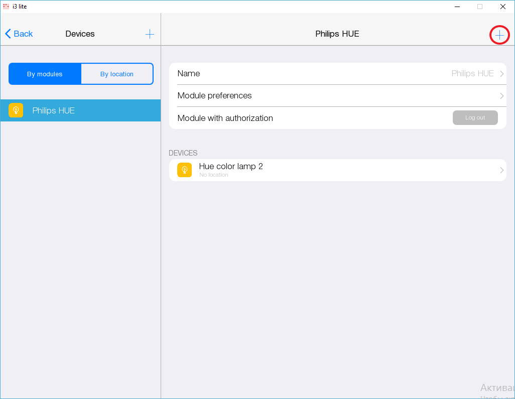
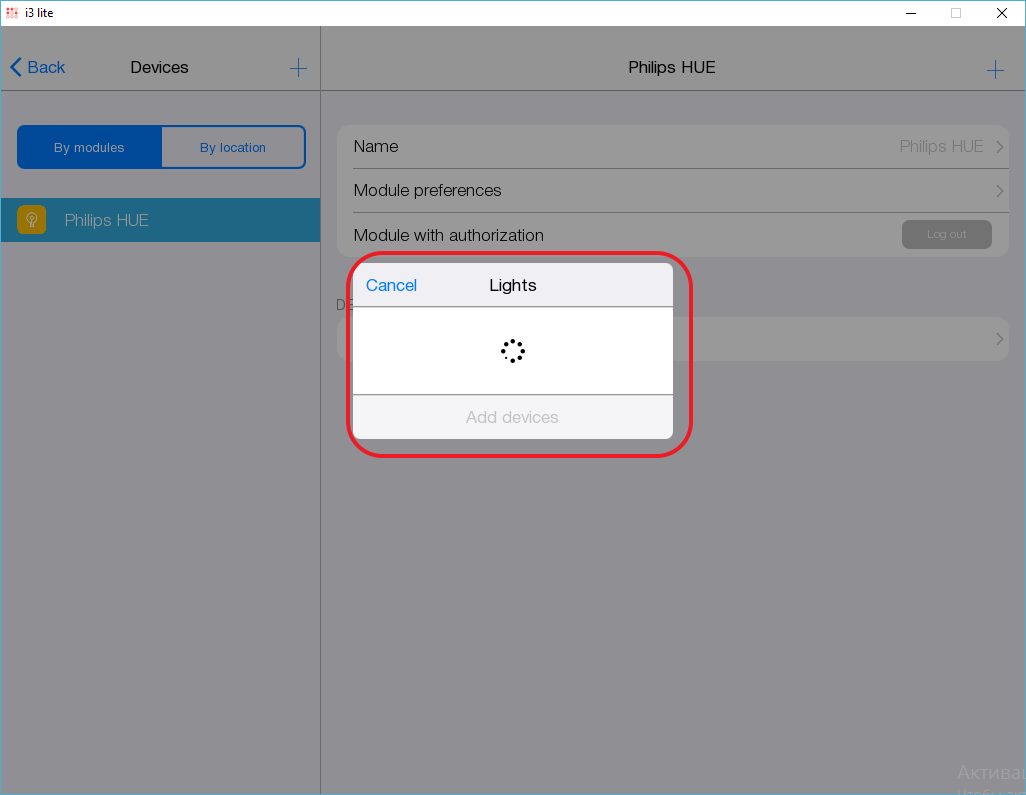
If the popup is assigned to the specified system variable, the user will see a "+" button in the module settings section. This button opens the specified popup
Example of specifying the adding subdevices window. When developing, you need to create an adding window in the tablet resolution and a separate window in the smartphone resolution
module.SettingsPopupName = IR.DisplayType != IR.DISPLAY_TYPE_TABLET? module.GetPopup("phone:NoAuthorize").Name: module.GetPopup("NoAuthorize").Name;
Authorization
To work with certain devices a user's authorization in a third-party system is required. i 3lite app has a special authorization mechanism for this purpose.
To authorize a user has to enter his access data in a special window. This window is unique for every device and a module developer must create it. A window to enter data is a popup with fields to enter data. The popup is created with the help of standard means of the studio and it may be unassigned to any subdevices. When access data are entered, the script must authorize in a third-party system and close the authorization window. After creating an authorization popup, a developer must call the authorization system variable in the script and assign the created popup in the variable.
AuthorizationPopupName = module.GetPopup("AutorisationPopup");
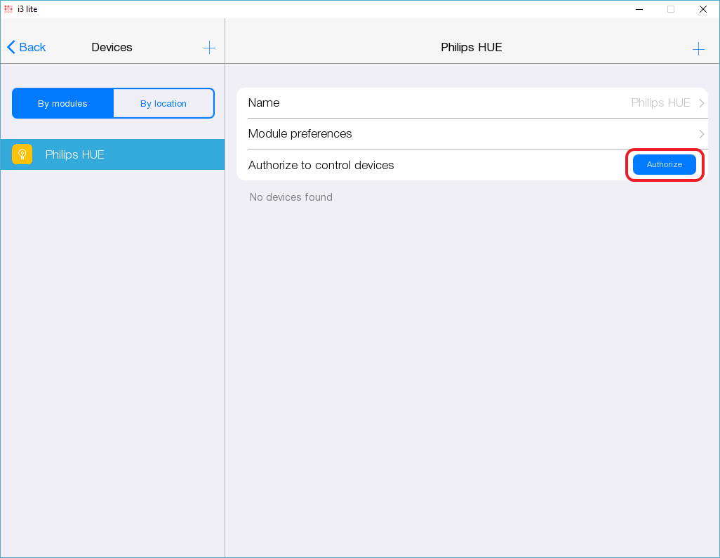
After an authorization popup is assigned to a variable, "Authorize" button appears in the module settings.
When this button is pressed, the app opens the authorization popup, assigned in the script. The next task for a module developer is to display a user's status (Authorized or not). There is a system variable to solve this task.
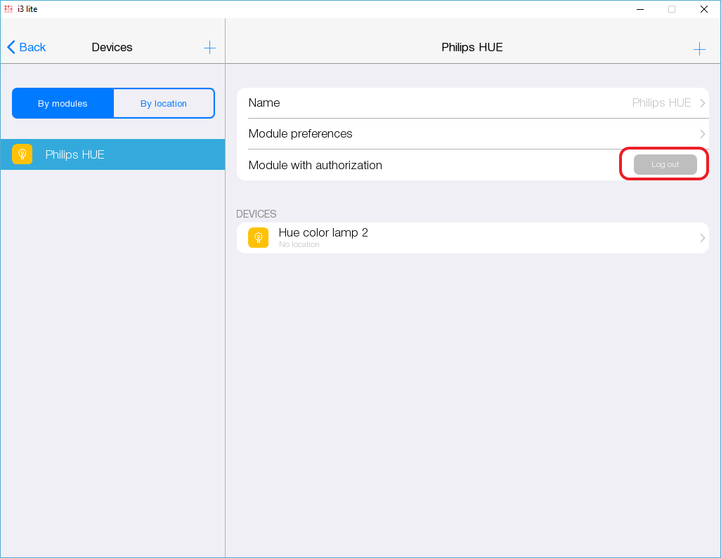
AuthorizationStatus = true;
If a user is authorized in the system, true value is assigned to the variable and the app changes the status of the authorization button into:
A module devloper must also think about the mechanism of deauthorization. It is done on the authorization popup.
An example of the authorization script
if (module.AuthorizationStatus  == false) { //If a user is not authorized
  module.AuthorizationPopupName = WindowSettings.Window.Name;//Assigning the authorization popup created earlier
} else if (module.AuthorizationStatus) //If a user is authorized
  {
	 module.AuthorizationPopupName = IR.DisplayType != IR.DISPLAY_TYPE_TABLET? module.GetPopup("phone:deAuth").Name: module.GetPopup("deAuth").Name;//Showing the deauthorization popup
  }
Note. Remember to create a separate authorization/deauthorization popup for a smart phone and for a tablet.
Changing settigns
While working with the application, there may be a need to change the settings of the module. To provide such an opportunity, the module developer must create a function to change the module settings and assign it to the system method
module.ChangeProperties = function (in_oSetup)
{
	Processing of new module parameters
}
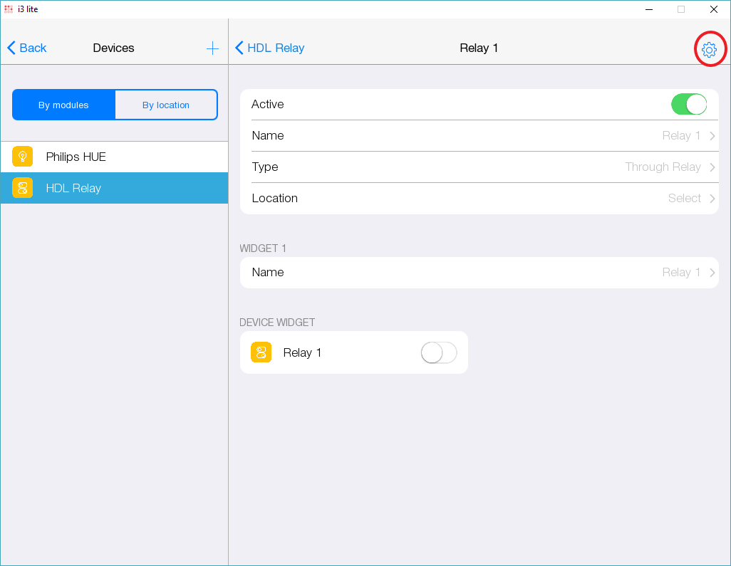
When declaring this function, the application will add an edit settings button in the module.
When the user clicks on this button, the application opens the Setup window that was used to install the module. In this window, the user enters new settings and presses the "Done" button. After that, the application runs the above function. The driver settings can be changed by the application itself, other module settings developer must change manually. New settings are written to the input parameter in_oSetup as a JSON line.
Also in this function you need to process the success of changing settings. The flag is responsible for this.
module.FinishUpdateSettings = true;
If the installation of new parameters was successful, then the value of the flag should be set to "true", and the opposite case should be "false". This allows the application to understand that the parameter change failed (if the status of the variable is "false") and the application will cancel the driver settings change, returning the old settings
Example of processing new module settings
module.AddListener(IR.EVENT_MODULE_START, 0, function(){
   module.ChangeProperties = function (in_oSetup, in_oModule) {
      if (typeof (in_oSetup) == "string")
         in_oSetup = JSON.Parse(in_oSetup);
            var l_nChannel = in_oSetup.Module["Channel count"];
      if (l_nChannel >= COUNT_CHANNEL) {
         module.FinishUpdateSettings = true;
         // Recreating element on cycle
         for (var count = 1; count <= in_nChannel; count++) {

            // Creating subDevice
            l_oSubDevice = module.AddSubDevice("Relay " + count, HDL_SERVER, false, IR.SUB_DEVICE_TYPE_THROUGH_RELAY);

            // Create revers
            if (!l_oSubDevice.GetProperty("Reverse"))
               l_oSubDevice.SetProperty("Reverse", 0);

            // Assigned to the variable name of the channel
            var l_sChannelName = "Relay:channel" + count;

            // Adding channels
            l_oSubDevice.AddChannel(l_sChannelName, Data);
            l_oSubDevice.AddTag(l_sChannelName, Data);

            // Adding smart virtual tag
            l_oSubDevice.AddVirtualTag("Power", 0, false, IR.SUB_DEVICE_TAG_POWER, true);
         };
      }
      else {
         for (var count = 1; count <= COUNT_CHANNEL; count++)
            if (l_nChannel < count) {
               var l_oDeleteSubDevice = module.GetSubDevice("Relay " + count);
               module.DeleteSubDevice (l_oDeleteSubDevice.ID);
            };
      };
   };
});
Typing a module using the Smart API
As you know, the modules allow the i3 lite application to control certain equipment, be it a Philips HUE lamp, an HDL switch or some other device. Without SmartAPI, the modules could only manage the devices for which they were designed. SmartAPI also allows you to develop modules that work with specific types of devices. Using this API, you can, for example, make a module that turns on / off all the lights in the house.

